WHITEPAPER
3D PRINTING GUIDELINES
Part One

B.Diallo
Don't forget signup to our newsletter below to keep up to date with the latest information to help you achieve better results. If you like the guideline, please share and if you have any topics you wish us to add, send me an email.
INTRODUCTION TO 3D PRINTING GUIDELINES
3D printing is one of those technologies that will and have drastically impacted the manufacturing industry. Many newcomers however come into the processing assuming it is as simple as pressing a button in order to achieve great results. Although partly true, users need to understand some 3D printing guidelines that need to be strictly followed so as to achieve reliable and great results. This part one of the guide will aim to inform and help users get acquainted with some of the basic steps to be aware of when aiming to get started with additive manufacturing.
These guidelines begin with the hardware involved:
1. Print Bed
2. Extruders
3. Hot-Ends
4. Enclosures
After the hardware aspect, users need to understand the most important aspects of the printing process :
5. Bed Adhesion
6. Model Orientation
Once users understand these elements, they need to master how they can manipulate 3D models before they begin printing to help reduce possible issues with their final models.
These elements are :
8. Slicer Software
9. Infill
10. Layer Height
11. Model Shells
12. Skirts
13. Brim
14. Support Material
After that, a basic understanding of some common issues that they will definitely face during the process.
15. Cracking
16. Warping
These are just a few 3D printing guidelines that will help you understand what the FDM process entails.
Part two will go further into elements such as the importance of temperature management, the intricacies of each 3d printing material and how you can start designing your own models that meet the requirements to be able to be printed.
What is Fused Filament Fabrication?
FFF has some advantages that make it suitable for various industries. Firstly, it allows for the printing of complex geometric models at low cost. It allows for design freedom for adopters that traditional methods such as CNC milling cannot accomplish.
Organisations would normally require high investment in either internal manufacturing machines or to outsource their tasks in order to achieve similar results, however, at a higher cost.
This makes FFF a suitable technique to enhance the product development cycle for any manufacturing organisation that is both cost-effective and can create high-quality results.
The demands of the global supply chain are increasing and firms want the ability to rapidly test out designs quicker and the standard process of waiting for a third-party vendor is no longer economically feasible.
Traditionally, outsourcing models and prototypes of parts would take up to weeks or months, in extreme cases.
Added to this wait time is the added cost of employing these techniques which can mean spending thousands of dollars to get a prototype of a part.
Additive manufacturing gives organisations the ability to perform rapid development fully in-house with full creative and development control, giving organisations the ability to develop products or parts extremely quickly.
3D Printing Approach & 3D PRINTER ADJUSTMENTS
There are various parameters and settings that are required to create an object using a 3D printer. Despite the ease of use in comparison to other manufacturing processes, a 3D printer still needs correct settings in order to achieve the desired printing result.
New users to 3D printing need to be aware that the setup before a print job is key so as to limit issues later on. A good first step is to understand is that the first layer of an object is the most important part of the printing process.
If this is neglected, then the issues that arise will compound and lead to deformed object. Below is an outline of the most important elements that users need to be aware of and also the key issues that can arise and how to properly prevent them from using the correct print settings.
FFF PRINTER PARTS AND ADJUSTMENTS
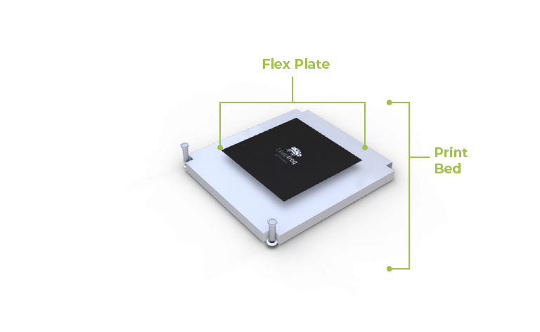
PRINT BED
The print bed is the area that holds the 3D printed object. It operates along the Z axis and descends to allow for the layering process. Different 3D printers use a number of materials as print beds.The most common are acrylic, glass or aluminium.
Print beds can also feature a heated surface which is designed to reduce warping of the object which is caused by different cooling rates at the base.
Heated beds are heavily advised to use when you need to reduce printing issues especially when working with engineering filaments.
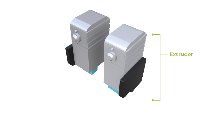
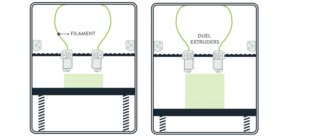
3D PRINTER EXTRUDERS
Extruders are the main components in a 3D printer. They are parts that allow for heat transfer to melt the thermoplastics and move around the printing space to create the 3D printed part via extrusion.
They operate along the X and Y axis in the print chamber and create the layers on the print bed. Many printers come either with a single extruder configuration or dual.
Single extruder printer models have limitations that need to be considered before the printing process, while dual extruders have the advantage of being able to print with two materials.
This feature gives users the option to use support material to help hold the thermoplastic object in place allowing for more complex objects which are a major consideration for single extruder setups.
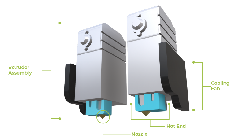
HOT ENDS
A hot end is the bottom part of an extruder and it is the location where the filament is melted and then extruded through a nozzle onto the print bed.
There are a variety of hot end types. Some are designed for high temperature extrusion and reduce heat creep. Others are required for certain materials due to the materials’ properties during the extrusion process.
Most hot-ends feature a heat break, a feed tube and heatsink. The top half of a hot end, has a heat break that stops heat creep from melting the filament at the top of the extruder where it is inserted. A heat sink is added to reduce heat creep.
As the the filament is pushed through by a stepper motor, it melts slowly and then as the extruder moves, each layer is added.
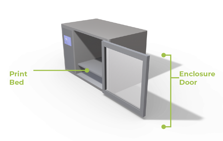
ENCLOSURE
FFF printers can have either an open setup or an enclosure system. Printers that have an enclosure allow for a number of advantages over printers that do not.
Firstly, enclosures provide better ambient temperature distribution which reduces fluctuations. This reduces cases of 3d printed objects deforming similar to the warping issue caused by different cooling rates.
Secondly, an enclosure limits 3D printing fumes that can occur with certain 3D printing materials. Some printers come with a HEPA filter that will eliminate this issue.

BED ADHESION
The biggest issues that can occur during the printing process can be reduced if the first layer process is calibrated correctly.
This is mainly a temperature setting issue and having a heated bed can help reduce issues such as warping.
Additionally you need to ensure that the layer sticks correctly to the bed to reduce issues that can occur with the layering process.
This can be done using special or standard glues that are purchasable online.
Another solution is to apply skirts or brims to allow for better printing results.
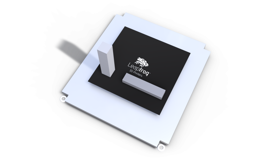
MODEL ORIENTATION
The print orientation is the direction that the object will be constructed through the layering process.
There are two possible directions, either vertically or along the X/Y axis (Horizontally).
The orientation that you print an object can affect its strength and overall structure. This is especially important for functional prototypes.
As you can surmise if stress is applied the same direction as the layering process, the weakest areas come about between the layers.
An example would be to use the standard tensile strength test on the vertical bar in the image, which will have a lower yield and failure point.
SLICER Software Adjustments
SLICING SOFTWARE
The creation of a 3D printed object begins with CAD software. There are different types of CAD software which differ in the process of constructing an object. Some work through using standard shapes (Solid Modelling), while others are work in the manner similar to sculpting of clay (Mesh modelling).
The differences are due to historical uses where certain software was designed for animation while others specifically for product development. Regardless of choice, most of the applications can export 3D model to popular formats that can be used for 3D printing, namely to STL files.
An STL file is a representation of a 3D object that is constructed using small triangles. It breaks down the CAD models’ surface into tiny triangles that combine to make the object. The size of the triangles are controlled by setting the resolution when exporting.
To illustrate this, a lower resolution object will have visible edges, especially along a curve, similar to the pixelation of a low-resolution image but in 3D space.
After the creation of the STL file, it is then imported into slicing software which converts the object into printable layers that the printer can map out. The slicing phase is a key step where all the desire parameters are added to create the desired fidelity of the object. These parameters can include for example the desired printing temperature, layer height and more.
After setting all parameters, the slicer software then creates a G-Code version of the object. G-code is a language that instructs the 3D printer on how to construct the sliced layers. It controls the different parts of the 3D printer such as movement of extruder within the print chamber.
Types of Infill
The infill is the inner structure of a 3D printed object. It can either be completely solid, or be made up of a patterned internal structure that uses less material but still offer certain properties.
There are a number of available geometric shapes that can be used as an infill with each offering certain attributes while reducing material use. The shapes are rectangular, wiggle, triangular and honeycomb.
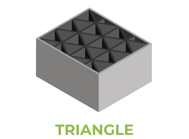
Triangular infill offers lateral load strength for 3D printed parts. Lateral strength is the ability of an object to resist lateral which gives better shell strength to the object.
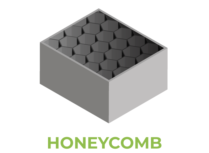
Honeycomb infill provides maximum strength with minimum material and can be printed relatively quickly.
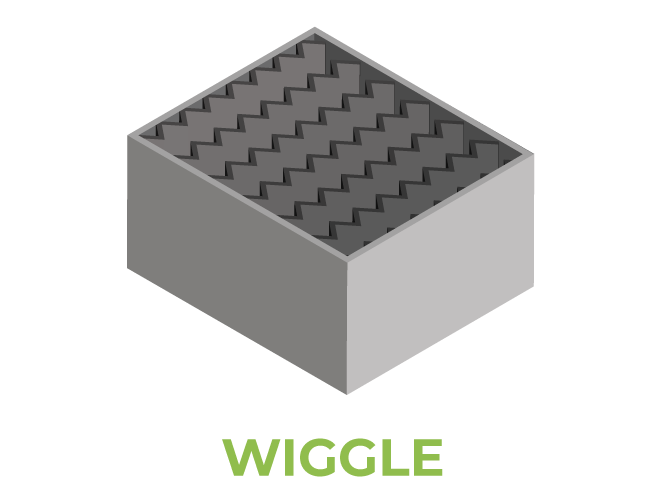
Wiggle is mainly used for flexible materials and parts since it allows for easier twisting and bending of the object.
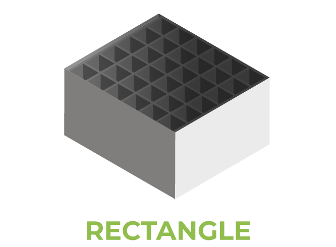
Rectangular infill is the default setting offered in many slicing software applications and this shape offers no special qualities in comparison to the others.
Depending on settings, the infill can usually be between 5% to 100% of the internal structure of an object. This setting is dependent on the desired requirements of the object.
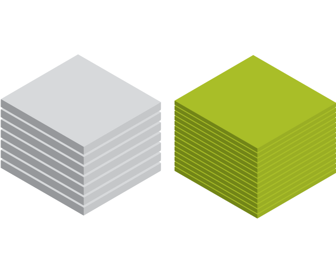
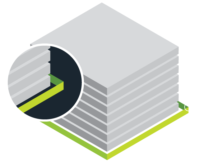
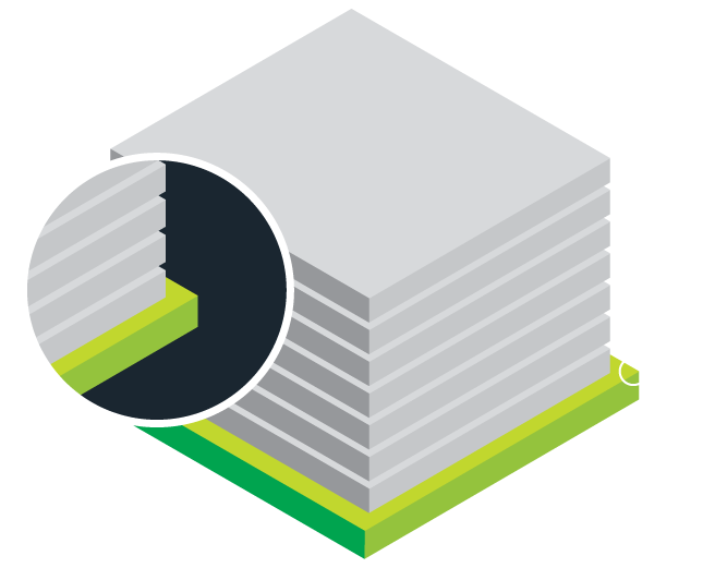
Layer Height
Layer height is a crucial aspect of the 3D printing process that requires careful consideration due to layer thickness having a notable influence on the overall structure, finish and strength of an object.
Larger layer heights lead to air gaps forming easier which has a major impact on the tensile strength of the 3D print.
The adhesion between layers is improved by decreasing layer height, however this impacts the overall speed of the printing process.
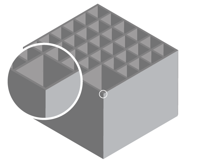
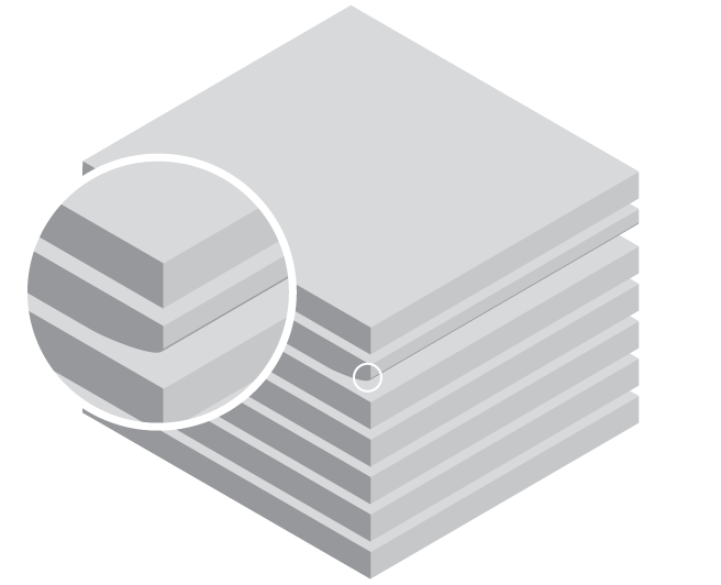
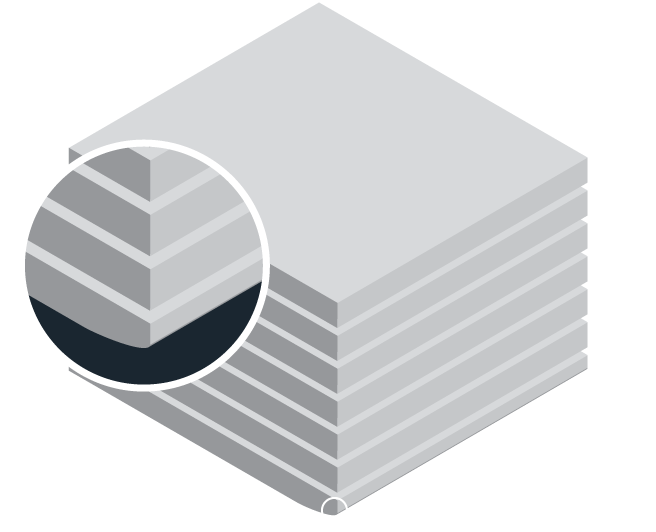
Shell
Shells refer to the number of layers that encircle the surface of the 3D printed object.
The shell encompasses the infill structure and can include one or more layers. Fewer layers allow for faster printing, but the strength of the object is reduced.
Another consideration to be aware of is post processing requirements for the 3D object. Post processing can be sanding or painting for example.
Thinner layer thickness will mean further post processing will affect the object’s strength properties, while having a thicker shell will add strength, rigidity but add weight to the object.
Shell thickness is dependent on the layer height chosen where a layer of four will be a multiple of 4 of the printing layer height.
Skirts
A skirt is a thin line that surrounds the print model but does not touch it. It is extruded before the printing process begins and it serves as a primer before the printing process can begin.
Due to the process of melting, molten plastic can be clogged in the nozzles and by printing it skirt first, it ensures all printing settings are correct.
This can be that the extruder/s are accurately calibrated at the right height from the print bed, but also to ensure a consistent material flow during the printing process.
Brim and Rafts
A brim is a skirt that is attached at the base of the print object at the perimeter. It contains a few more outlines and it is used to hold up the edges of a model. This is both for objects with narrow footprints or objects that have significant bottom surface areas.
A raft on the other hand is printed first and then the object sits on top of it. It carries the object and is mainly used for materials that have a tendency of warping like ABS. It provides better adhesion for parts ensuring that object stays firm and additionally stable during the print process, especially for very narrow parts.
The choice between Brim and Rafts is dependent of requirements. Brims are a lot faster to print and also require less material while Rafts provide the best support and stabilization for the printed object.

Support
The usage of support material has one main purpose. The major advantage of 3D printing is the being able to produce one part that can have hollow or complex geometries without need to machine it multiple times or require gluing of multiple parts together. This is achieved because of the ability to print support.
There are two categories of support material. The first is breakway support that uses the same material as the object, normally used in a single extruder 3D printer. In the Slicer software, support is added where it is thinner at the connection point between it and the model. This makes it easily removable after printing using a cutter plier.
The second category is soluble support such as PVA or HIPs. This requires a dual extruder 3D printer but the advantage is you do not require difficult post process, where all you need is to submerge the model in the required liquid and the support dissolves away. This method produces the best results with the least effort.
COMMON 3D PRINTING ISSUES
Common Issues
Fused Filament Fabrication printers come in two popular varieties.
The first having a single extruder while others can have more extruders with the common denominator being two. An extruder consists of a cooling fan, a motor, heated nozzle that pushes the melted filament out on to the print bed.
Single extruder printers can print geometric complex objects; however, they do not offer the option to print with support material. This can be a major disadvantage when printing objects with overhangs that are greater than 45 degrees.
Having dual extruders gives more versatility during the printing process.
FFF printed objects are anisotropic which means that most of the strength of the object will be perpendicular to the layering direction.
Cracking
Cracking is caused by the same issue as warping, being the non-uniform cooling of a printed object. The difference of cracking from warping is cracking occurs at different locations in the printed object.
To offset the possibility of cracking, a printer with an enclosure allows to eliminate the ambient temperature fluctuations that may occur that could lead to cracking of a 3D printed object.
Warping
Warping can be described as the shrinkage of a 3D printed object at the corners of the base, mainly attributed to temperature changes.
Warping is due to the process of non-uniform cooling where certain printing layers cool faster than the heated parts.
When this occurs, the cooler layers end up distorting the objects geometry since cooling causes shrinkage and this action affects the immediate molten layers.
As the areas cool and harden, they pull on other layers as cooling increases.
The main reason for warping is heated thermoplastics need uniformed cooling after being extruded to allow an object to accurately settle while maintaining the desired geometry.
If the printing bed is not heated or the ambient temperature of the print chamber is not modulated then this leads to different cooling rates.
To prevent warping issues, ensure that the FFF 3d printer has a heated bed with a metal plate. This distributes the heat throughout the bed and means a more uniformed temperature distribution.
This will minimise the effects of warping in the first layers of the object.
This is the end of part one. Be sure to signup to the newsletter to get the latest updates.
NEWSLETTER
Subscribe to our weekly newsletter for useful tips and valuable resources.